Conflation of two data-sets
Overview
This page provides an overview of the cadastral process commonly described as Conflation. This is a common workflow performed by custodians when they wish to upgrade or align their data sets with other external data. Often, intensive manual processing is required to bring new business data into alignment with the current cadastral release (or vice-versa). myCadastre solves this problem by providing a series of proprietary topology matching algorithms that provide unrivalled capability to automatically match common features between the two cadastral datasets. Shift vectors are automatically generated which then allow for subsequent re-alignment of all other spatially dependent layer e.g. administrative layers, road centrelines, text, annotation, etc.
Case Study - UNDER CONSTRUCTION, ignore below
The following outlines a specific subset of processes that we have applied to an example CEXML survey plan.
The data used is:- CEXML files supplied by the Northern Territory Department of Lands, Planning and the Environment
- surrounding base cadastral fabric for the suburb of Driver, including the parent parcels that the CEXML affects
- all data and application functions were executed as REST calls against our AWS (Amazon Cloud) instances (PostgreSQL/PostGIS Database and application server).
- screen shots were acquired via QGIS looking directly at the cloud database using a VPN connection.
- all REST calls were invoked from our desktop client
Goals
- To automatically load and process the supplied CEXML file
- To demonstrate the downgrade Fit to Fabric component process of the myCadastre software suite.
- To retain all measurements abstracted from the CEXML datafile in database tables that will be used as source data in later adjustment actions.
- To prepare the base cadastral fabric for update with the new CEXML parcels.
The Fit to Fabric process represents common practice amongst custodians trying to avoid the supply of continuously changing update data out to client organisations. This is to avoid the situation or creating continuous and ongoing downstream data re-integration in the supply chain. It is a much preferred practice that custodians Upgrade larger blocks of cadastral data on a programmed basis; and then supply that new data to clients along with the relevant shift-vector data set (to facilitate asset re-alignment).
Walk Through
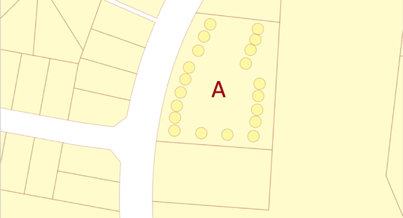
Working with the original parcel fabric, the following serves to demonstrate load, shred, auto locate and process the supplied CEXML file into the parent fabric identified by 'A'
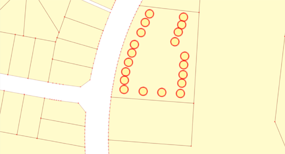
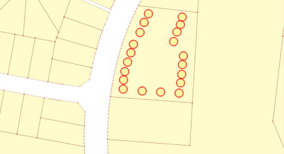
Showing nodes and point data
Same area showing existing point data. Curved boundaries are represented by arc segments (which is the typical case in most current GIS based cadastres)
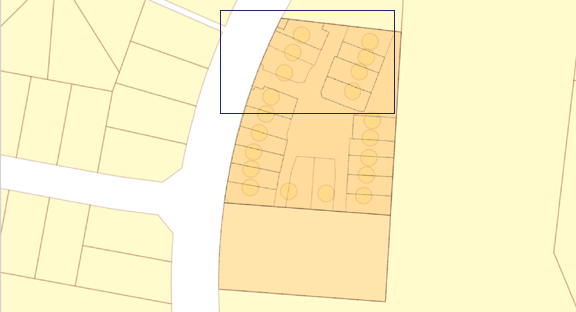
Shred data and store to database
The CEXML file has been read into the system and shredded. This means that the file has been broken down into its many constituent parts and stored to database tables. At this point in time, the CEXML plan is rendered as lines and polygons (in orange) overlaying the base cadastre.
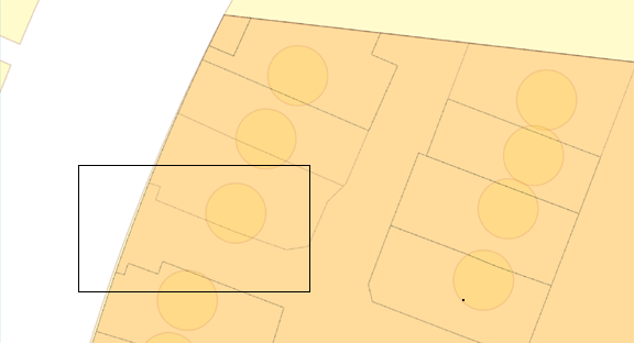
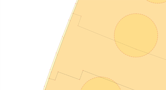
Checking for mis-alignment
Zooming in to the top North Western corner, the area framed in blue in the above diagram, shows a growing discrepancy between the CEXML location for the curved western boundary and that of the existing cadastre.
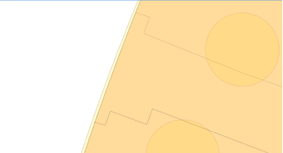
Discrepancies
Zooming in even further, to the blue rectangle above, clearly shows a misalignment between the two boundaries.
Performing the Adjustment
The next action is to invoke a REST call to generate shift vectors between the original cadastral parcels and the newly onboarded CEXML survey data. These are generated automatically and usually results in a greater than 95% match against the existing Cadastre.
At this point in the processing, we would usually perform a brief eyeballing of the shift vectors to ensure that there are no obviously erroneous ones (and would delete those). In addition, whilst doing this, if we develop a sense that a little bit of assistance might be needed to facilitate the next stage of processing, we might also choose to add additional shift vectors via manual snapping.
We then perform an adjustment on the data (as limited as it might be at this point) in order to obtain the best all round shape on the newly submitted CEXML parcels. Three types of adjustment are facilitated:
- An iterative best guess (IBG). This is quasi least squares but does not require a full complement of observations in order to determine and solve a system of observation equations. The results from an IBG are generally acceptably close to those obtained via a full least squares adjustment.
- A least squares adjustment (LSA) which can be used when there are sufficient measurements (and redundant observations) available to make proper use of this method.
- A similarity transformation
Once we have performed an adjustment, we then invoke our conflation routines. These routines make use of the shift vectors to bring the main cadastral corners (nodes) into coincidence. Further calculations then follow to re-incorporate any boundaries with arc parameters and to insert any newly created node points along the arc.
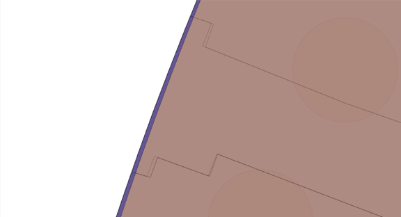
Post adjustment
The resulting (downgraded) plan, shown in purple, can be seen to have needed to stretch the new plan features to match the original Western boundary.
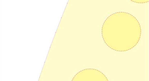
Boundary arc vertices
Image showing the vertices for arcs in the original base Cadastre. This is in the pre-reconcile phase between newly computed amd reconciliation actions.
Boundary arcs and new nodes
Showing the vertices of both the original and the CEXML plan features, as loaded. Clearly seen, is the shortfall in the new plan image data relative to the existing cadastre.
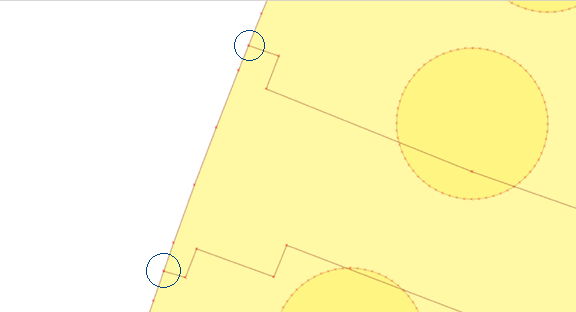
Final stage
On the Western boundary (along the road frontage) the original cadastral vertices have now been adopted from the original cadastre. Only the two new parcel nodes (circled) are added at the point(s) where the boundaries intersect.
Re-cap
The original cadastral data without the strata title boundaries shown. It is a common occurence across the jurisdictions that strata infill is not available in digital form.
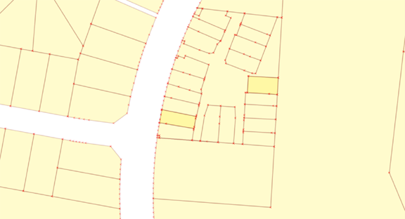
Final state
Showing the new cadastral boundaries fitted automatically to the underlying cadastral fabric. All that remains from here is for the new configuration to be reconciled back to the authoritative cadastral database.
Conclusions
This case study demonstrates an automated process to:
- Load digital plans from an agreed standard format (in this case CEXML)
- Shred the data and save the plan features and dimensions into the survey database
- Match the new survey plan to existing Cadastral features.
- Downgrade or 'fit-to-fabric' the newly ingested plan to align with the existing cadastral parcel(s) that it supersedes.
- Prepare the new plan for reconciliation to the base fabric in order to provide an updated Cadastre
Once sufficient dimensioned plans have been inserted into an area, the myCadastre solution can be used to simply and efficiently improve the spatial alignment of the cadastral fabric by running either an 'iterative best guess' or a rigorous 'least squares adjustment' based on the stored plan dimensions and connections to survey control. This would be a simple addition to this case study when more CEXML files for the Driver suburb are available.
Additionally, if digital plans are not readily available (either new or current Cadastral plans), the myCadastre cCogo Capture tool can be used to efficiently capture all required plans. Being web based the cCogo can be provided to any stakeholder with an interest in improving the spatial accuracy in an area.